The VSPS
The Very Simple Phono Stage (2017 version)
Presenting a simple, versatile phono stage for moving magnet or high output moving coil cartridges using a bare minimum number of parts and the following features:
- Low parts count makes it cheap to build and easy to optimize.
- Wide choice of op amps. Just about any op amp can be used in this circuit.
- Accurate RIAA equalization obtained using common, standard value components.
- Low power consumption.
This circuit is appealing for beginners, of course, but the simplicity also offers more experienced builders the chance to evaluate and optimize each individual part. The VSPS is the most popular circuit I have developed, many people have successfully built it. It's a proven, rugged, and reliable project.
The Amplifier Circuit
An op amp is configured as a non-inverting gain stage. The RIAA equalization is part of the feedback loop. This is a classic circuit, but not seen too often in DIY audio since calculating the resistance and capacitance values needed can be a pain.
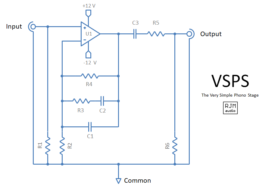
The circuit is otherwise so basic that each component can be discussed individually.
| Component | Value | Description |
|---|---|---|
| R1 | 47k | This resistor (and optional capacitor) should be set as directed by the cartridge manufacturer. |
| R2 | 680R | This resistor sets the gain. Lower values result in more the gain. Use 2.2k for 30dB, 680R for 40dB, and 220R for 50dB. |
| R3 | 110k | RIAA. Match between channels. |
| R4 | 768k | RIAA. Match between channels. |
| R5 | 47R | Isolates the op amp from the effects of output lead capacitance. |
| R6 | 100k | The value of this resistor isn't critical, it mainly serves to drain off charge from the output side of C3. |
| C1 | 1.00n | RIAA. Match between channels. |
| C2 | 3.00n | RIAA. Match between channels. Use 3x 1nF in parallel. |
| C3 | 2.2µ | Output coupling. Must be non-polar. |
| U1 | NE5534 or OPA134 | Any audio op-amp could be used with satisfactory results. Stereo layouts require dual op-amps e.g. NE5532, OPA2134. |
RIAA values shown in bold.
With the circuit values as given above, the accuracy of RIAA response over the audio band is within ±0.2 dB.

Construction Notes
The phono preamplifier circuit is powered by regulated, low noise, split 12 V supplies. Normally the voltage regulation and filtering is placed on the same board as the phono circuit. The power transformer and rectifier diodes are typically in a separate chassis connected by an umbilical cable. The Construction Guide explains how to put everything together.
Circuit Board
Circuit boards are available for this project. The stereo circuit is contained on a single board, and includes LM7812, LM7912-based voltage regulation and power supply filtering. Only the power transformer and rectifier diodes are off-board.
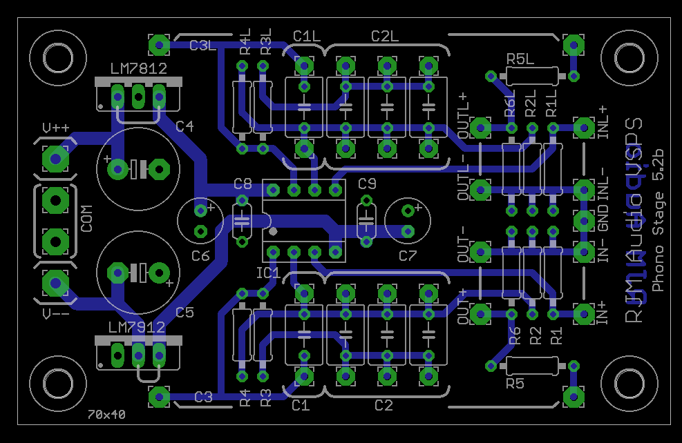
The stereo VSPS circuit board.
Design Manual / Schematic Files
rjm003.geo at yahoo.com