Construction Guide
Hints and tips for building RJM Audio projects.
When working from the printed circuit boards (PCBs), the most important thing is to first check you have the most recent version of the Bill of Materials (BOM) worksheet, an Excel file packaged as a Zip archive normally linked to from the PCB page. This file gives you the parts list, calculations, and operational notes. Then you need to decide the details of the build such as the chassis, power supply, layout, I/O etc. Source the parts, double check the layout, drill the chassis, solder the parts to the board, wire everything up, test, and troubleshoot, and by the end you should have a working audio component. If I had one single piece of advice to give, it would be simply this: Read first, solder later. It is far easier to prevent a mistake than fix it.
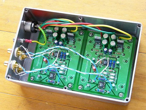
Completed Phonoclone B.E. boards fitted in a Hammond 1590D aluminum project box.
The Power Supply
The basic power supply unit consists of a 25~50 VA power transformer with two 12 VAC secondaries and two bridge rectifiers. No filter capacitors are required, but things like a fuse, switch, and indicator LED are typically installed in the power supply chassis. The power supply can be external or internal. With all boards except the stereo VSPS the power supply can be dual mono. Transformers with electrostatic screen and magnetic shielding are recommended. Note that COM does not connect to the power supply chassis.
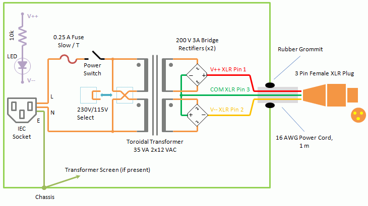
General outline for the external power supply.
Sourcing the Parts
BOM files have lists of the parts numbers at Mouser which can be copied into an order directly using the Mouser's BOM importer tool. Of course you can substitute parts freely from any supplier, using the same brand of part is never required. Audio specific, upgraded parts like coupling capacitors can be obtained from specialty retailers like Parts Connexion.
Soldering the Circuit Board
Place the soldering iron tip on the pad first for a second or two to heat that up before moving the tip slightly so it contacts both the pad and the lead wire. Wait a further couple of seconds to get the wire locally hot before applying the solder. Of course getting the timing right is a matter of practice, but investing in a good soldering iron with temperature control (Hakko, Weller, etc.) makes the job ten times easier. The PCBs have heavy 2 oz. copper ground planes so low power irons will have a hard time of it.
Components are soldered in order of height, from shortest to tallest. Resistors and diodes first, transistors and electrolytic capacitors last.
Hooking Things Up
Mounting: There are mounting holes at each corner of the board, 3.3 mm in diameter. The board is attached to the case by standoffs and either M3 or 4-40 machine screws.
Connections: IN+ and IN- go directly to insulated input RCA jacks. OUT+ and OUT- connect to insulated output RCA jacks or headphone jack. V++, V--, and COM go to the power supply. When two COM pads are offered the wires from the COM connection from individual bridge rectifiers may be taken separately right to the board instead of joined together earlier. The GND pad of each board is normally connected to the case.
Example connection diagrams for stereo and single channel phono stage boards, having either shared and independent power supplies:
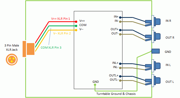
Connection schematic for a single stereo board.
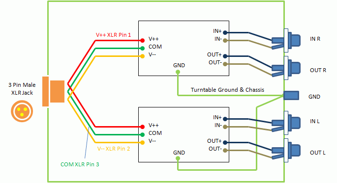
Connection schematic for two single channel boards with a shared power supply.
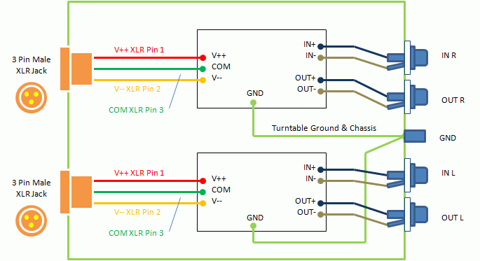
Connection schematic for two single channel boards with separate power supplies.
Please consult the VSPS and Phonoclone Help Desk at diyaudio.com for additional help and discussion, together with many photos of completed projects.
rjm003.geo at yahoo.com