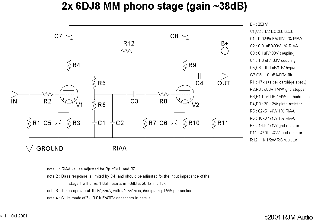
A simple phono preamp using a pair of 6DJ8 (ECC88) tubes.
Two conventional triode voltage amplifiers and passive RIAA equalization.
A phono pre-amplifier having a gain of about 40 dB, passive RIAA equalization, two tubes, and simple circuitry. The 6DJ8 (ECC88) dual triode tube was chosen for its relatively low output impedance, reasonably high gain, and ready availability. The operating points are set conservatively to ensure long life and high reliability. I wanted to design an easy to build, easy to use, easy to power, and easy to listen to device.
The Amplifier Circuit
Circuit walk through:
The input signal from the cartridge is fed into the grid of V1, through a 500 ohm grid stopper resistor R2 to prevent oscillations. V1 multiplies the signal by about 30 times. It is then equalised to the RIAA standard curve by a frequency-variable voltage divider which drops the signal voltage by a factor of 10 on average. This is essentially the same voltage divider network found in the previous project, the op-amp phono stage. The output is capacitively coupled through C3 to the next gain stage, with another grid stopper resistor R8. R8 is not optional; the amplifier will oscillate otherwise. V2 multiplies the signal by another factor of 30. The output from the plate of V2 is coupled through C4 to block the DC voltage before being routed to the output RCA jack. Total gain about 30 / 10 x 30 = 90.
The RIAA equilization network comprising R5, R6, C1, C2 is set taking the output impedance of V1 into consideration as well as the grid resistor R7. C3, C8, R8 and the miller effect in V2 may be safely ignored. The MathCAD model shows a linear response ±0.1 dB over the audio band, with the normal roll-off at both extremes caused by other circuit considerations. This was confirmed on the test bench, the measured deviation being within ±0.2 dB 20 Hz - 20 kHz.
As always there is some benefit to using high quality components, especially the cathode bypass capacitors C5 and C6. Audio grade electrolytics here, and polypropylene, polystyrene or audio-specific coupling caps for the rest of the capacitors. As for tubes I have used the Amperex Bugle Boy 6DJ8s and would recommend them. They seem to be a smooth sounding, low noise tube. Mullard brand 6DJ8s are very similar.
| Recent Revisions : The power supply is filtered through R12 before V1. This additional filtering is chosen to exactly balance the gain, so that maximum noise cancellation occurs at V2. This works very well, as the phono stage is very quiet. |
| Design Note : Bass is controlled by R5 in series with the output impedance of V1. The larger these values, the greater the bass in the 50 Hz - 100 Hz region. If the operating point of V1 is changed, then the output impedance will also change, and R5 may have to be adjusted to compensate. |
| Construction Note : I set this up with an external power supply, with only 2x 8 µF of Solen polypropylene B+ filter capacitance for each channel within the amplifier itself. The wiring was a mostly point-to-point, but the RIAA section and plate resistors were mounted on a single piece of perf-board. The only warning concerns the 30 kohm plate resistors R3, R10. They dissipate just under 1 W each, which is enough to get a 3 W wire-wound resistor too hot to touch. Allow for some air circulation/heatsinking if possible. |
The Power Supply
I'm particularely proud of this simple MOSFET regulated power supply. Nothing fancy, it just removes the ripple from the B+ with the minimum of fuss and bother. The principle advantage, besides a ripple of under a millivolt, is the trivial amount of capacitance needed to get there. An all polypropylene or oil capacitor power supply is quite practical, as is an ultra-compact one if electrolytics are used.

C1 and C2 can be reduced to 8 µF, C3 can be lower as well, set according to the method outlined below. C4 can be larger, but the total output capacitance (including whatever is included on the B+ next to the preamp circuit, should not exceed 50 µF.
The MOSFET should be rated to a voltage greater than 1.4 times the transformer output, but can otherwise be substituted at will. Anything in the IRF 7xx and 8xx product families will be suiteable. Buy at least two, as it is fairly easy to fry them when your project is in the prototype stage. Once connected properly they are very reliable.
The choke is needed to convert the ripple from a sawtooth wave typical of a capacitor input filter to a smoother sinusoidal waveform which is easier for the MOSFET to erase. 5 H - 20 H is needed. The erasing part happens because the ripple causes the gate-source voltage of the MOSFET to change, and the gain/transconductance of the MOSFET is large enough that it compensates almost perfectly.
The gate-source voltage is only a couple of volts, so the voltage at the junction of R1 and R2 is essentially the same as the output voltage. R1 is adjusted to get whatever voltage is required. The greater the drain-source voltage, the better the regulator copes with large ripple voltages and widely varying current loads, but the power dissipated by the MOSFET will be greater, requiring better heatsinking. Since the line ripple voltage and the current load variation are both very small in line audio circuits, a 25 to 50 V drop is more than enough. The power dissipated by the MOSFET is voltage drop x the current draw of the load circuit. It is about 4 W in the circuit shown, but only 1.5 W when driving just the phono pre-amp, which draws 20 mA.
This isn't an IC regulator like an LM7812. There is no absolute regulation, as there is no voltage reference. Neither is there any short circuit or thermal protection. It is better thought of as an unregulated power supply with really good filtering and very low output impedance than a true regulated supply.
For all its simplicity, there are a couple of useful side effects. When switched on, there is an initial turn on delay before the output voltage is at maximum. The time constant is equal to R1 x C3. This is also the low frequency cutoff below which the regulator does not function, so should be kept above 50 ms (10 Hz or less).
I consider the absence of an inherently noisy voltage reference (Zener or gas discharge tube) more or a plus than a minus, as I do the absence of feedback. The filtering is so good that the B+ can be applied directly to the plate of the input tube without needing a dropping resistor and extra filter capacitor, the result is fewer parts and a lower power supply impedance.
The supply is scaleable to larger voltages and currents, and it is easy to have separate regulation sections for each channel or even each tube. And yes, you could use tubes in the power supply too, and it might be even better. The solid state diodes could be swapped for a 6X4 or 6CA4 rectifier tube, but you'd need a center-tapped 650V power transfomer. The MOSFET could be replaced by a power triode, but to get the current capacity you might have to use one for each channel, and the gain might be too low, requiring a voltage reference and comparitor triode amplfifier. In short, do-able, but not quite as elegant. For a great discussion of tube voltage regulators, see the TubeCAD Website.
(Another) Power Supply
This is the power supply I use. 6CA4 tube rectifier, and an LCLC filter instead of the MOSFET. Less trouble, less noise, less hum, and better sound. The chokes are not expensive, since the current is so low. I use 22 µF Solen polypro caps for C1 and C2. The output is about 250 V. C3, C4, L3, L4 are just to try and remove high frequency hash, and can be considered optional.
