The Sapphire Desktop Headphone Amplifier
Full discrete transistor current feedback amplifier.
Current Feedback Amplifiers
The Sapphire is a classical current feedback amplifier (CFA) optimized for operation at audio bandwidths. The basic CFA topology has three stages, as shown:
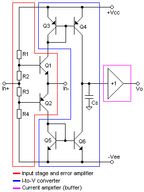
Current feedback amplifier circuit topology. (Wikipedia)
Using the wikipedia schematic as a starting point, the Sapphire is obtained by substituting input transistors for R2, R3, removing Cs, and adding a Vbe multiplier between Q4 and Q6 to bias the output buffer stage. The output buffer is the same class-A Sziklai pair headphone driver used in the previous Sapphire circuits.
In a classic CFA the feedback is taken from the output, Vo, but it is also possible to make the connection internally from the node connecting Q4 and Q6. We will call these configurations closed loop and open loop, respectively. The Sapphire allows both options. Open loop has more distortion, closed loop less stability.
What the CFA brings to the table so far as an audio amplifier is concerned is exactly what makes it rather difficult to understand relative to traditional voltage feedback. In either case the feedback network is a voltage divider made up of two resistors. With voltage feedback it's the ratio of the resistors which sets the gain, and by setting the gain, the bandwidth and the amount of feedback is simultaneously fixed. The open loop gain is already determined. In a CFA the open loop gain depends on the value of the resistors used in voltage divider, so, essentially, the bandwidth and the amount of feedback can be tuned to the desired value for any chosen gain. Basically, CFA gives the designer and indeed the end user much greater flexibility in optimizing the circuit.
The Circuit
The amplifier schematic is as follows.
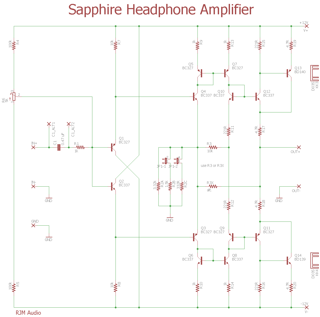
The volume control, typically 25k, connects to IN+ and IN- and is not shown as it is normally front panel mounted. R4,5,6 provide input offset bias adjustment to trim the output offset voltage. Next is a four transistor "diamond buffer" input stage Q1-4, followed by current mirrors Q5-8. Q9,10 and R11,12 comprise the Vbe multiplier, while Q11-14 is the Sziklai output stage. R2 and R3 or R3X complete the feedback loop. Using R3 puts the buffer out of the feedback loop, while using R3X makes the classic CFA closed loop connection.
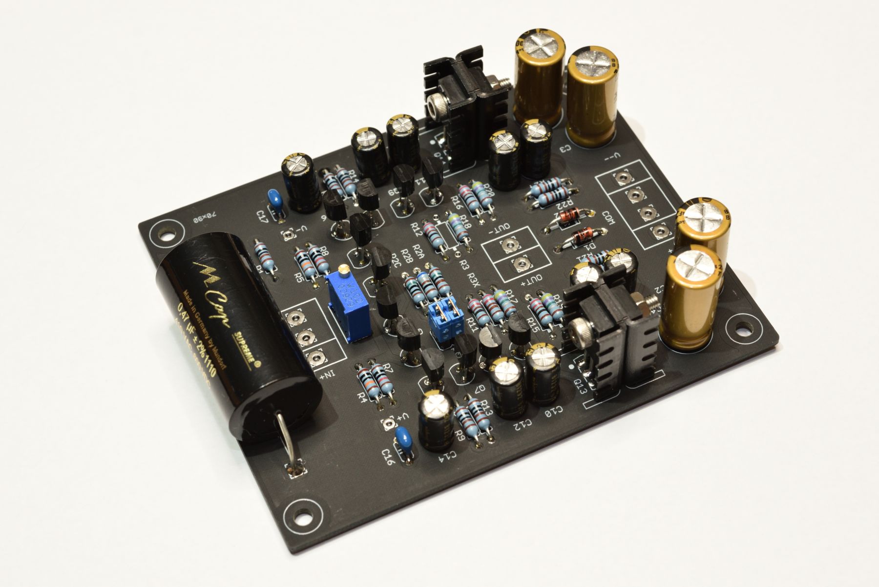
Circuit Board
Dual mono, dual sided circuit boards have been designed for this project. Z-Reg voltage regulation is included on the boards, which are powered by unregulated supply voltages V++ = 18 V and V-- = -18 V, just the same as the VSPS and Phonoclone projects. The output offset voltage is trimmed with R6. Either R3 or R3X is populated for open loop and closed loop configuration, respectively. Jumper JP1 provides optional gain selection as, see BOM for details.

The Sapphire circuit board, one channel shown.
Design Manual / Schematic Files
Build Notes
My chassis is starting to look a bit of a mess, especially after upgrading from Triad VPT to VPM medical grade transformers. Volume control is a Goldpoint V24-25K unit. The aluminum chassis, off ebay, has internal dimensions of width 180 mm and length 265 mm. Bridge rectifiers are KBPC2510.
