A JFET-MOSFET Headphone Buffer
Overview : Components : Development
Overview
The J-Mo Mk. I. buffer is based on a single-ended MOSFET output stage configured as a source follower, driven by a JFET source follower. The power supply is choke regulated. The circuit is configured for low impedance headphones like my 32 ohm Grado SR60s.

The amp offers 20 Hz - 20 kHz ±0.25 dB frequency response into a real headphone load, and a constant output impedance of 3 ohms. It is a robust and reliable zero feedback, class A circuit.
Components and Circuitry


There is a small trimmer resistor to equalize the bias current though the 10 ohm MOSFET source resistor. The typical output bias is 200-300 mA. (2-3 V across the source resistor) MOSFET must be heatsinked to dissipate about 3 W, while the source resistor should be 2 W type or higher.
The IRF510 was chosen for the low input capacitance, and recommended on that basis. Datasheet. The 2N4416 JFET can be substituted. Look for an datasheet Idss of 10 mA or so, and adjust the source resistor until Vgs is about 1/3 of Vgs(off).
The entire power supply can be replaced with any regulated power supply of between 12-15 volts at 1 amp.
This project was based on Greg Szekeres' MOSFET Buffer.
Sonics and Development
Frequency response can be adjusted to taste. The MOSFET's gate resistor acts with the MOSFETs input capacitance to create a low pass filter. Increasing the value of the gate resistance will cool off a bright or too prominent treble.
The bass response can be rolled back by removing one of the output coupling capacitors, or decreasing the capacitance value. Adding more capacitance does not increase the bass, but reducing the treble as described above will subjectively produce more bass.
There are many changes which are audible but probably not measurable. The quality of the coupling capacitors for example. I recommend trying 0.47 µF or 1.0 µF polypropylene for the input, and low inductance electrolytic capacitors such as the inexpensive Panasonic FC (digikey) for the output. Audio-grade upgrades may be a worthwhile.
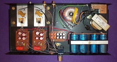
The power supply is a old school choke input type: toroidal transformer, diode bridge, choke, and a huge filter reserve for low ripple. There are also several 470 µF electrolytic bypass capacitors on the supply rails for each channel. Strategic placement of film and small electrolytic bypass capacitors may affect the sound, but when they do it will be in a largely unpredictable way.
Yes, the sound. Due to its flat frequency response, low noise, and other audiophile goodies (soundstaging, tonal balance, lack of grain...) I recommend the circuit, and I feel that it can - with patience - be developed into a reference class component. The amp can be tweaked to sound bright or dark, warm or cold. At this moment, mine is rather full sounding, with expansive, slightly loose bass. The highs are extended but not shrill, with a slight burnished quality to them. Overall it is sweetly musical, the way I like my audio. Never satisfied, I may look into modifying the output coupling to batten down the bass a little, or make further minor adjustments to the bypassing scheme, but it's 95% of the way there, which is why it's here, on the web site, with the RJM stamp of approval.
Note added much later: The resistive-loaded MOSFET source follower has a dominent second harmonic distortion component, and a very wide clipping behavior. That is to say distortion starts to increase well below actual clipping, but its a very gradual, natural progression favoring the lowest harmonics. Its not the most transparent amplifier out there, but what it adds makes the music sound better, not worse. A fundamental limitiation with the circuit is the absence of any voltage gain. A more recent version, the J-Mo Mk. II, takes another look on the basic configuration to optimise efficiency and distortion figures, and add voltage gain.