The Phonoclone!
47 Labs redux.
The Model 4712 Phonocube from 47 Laboratories is an op-amp based phono preamplifier for moving coil cartridges. The gain of the original is extremely high, 75 dB or 90 dB, and, mysteriously, the input impedance is given as "zero ohms". Interesting. Well, we cracked the DAC and cloned the 'Card, so why not try and copy the 'Cube?
Important Note: although the gain of the phonoclone is adjustable down to about 60 dB or so, this schematic will only work with low output, low impedance, moving coil phono cartridges. For moving magnets and high output moving coils please see the VSPS project.
The Amplifier Circuit
Zero input impedance seems strange, but there is a way to acheive this with op-amps and still measure the cartridge output. Consider the simple inverted topology:
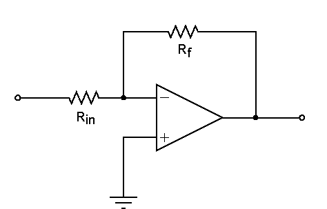
The inverting terminal is a virtual ground, thus the input impedance is just Rin. When Rin is removed the input impedance is zero. The amplifier becomes a current-to-voltage (I/V) converter. The MC cartridge is a voltage source, however, and when connected to the input of the I/V converter the net result looks like a standard inverting amplifier again, only with the input resistor replaced by the internal impedance of the cartridge Rs.
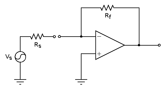
The voltage gain is Vout / Vs = Rf / Rs, where Vs is the open circuit output voltage of the cartridge. A "zero impedance" input stage allows an inverting topology to be used without adding extra noise generated by the input resistor. The impedance of the cartridge must be relatively constant over the audio band, however, or else the frequency response will deviate significantly from the manufacturers specification.
The Phonoclone, the following 13 part circuit, is the input stage described above coupled to an inverting output stage. Somehow it all fell together once I got started.
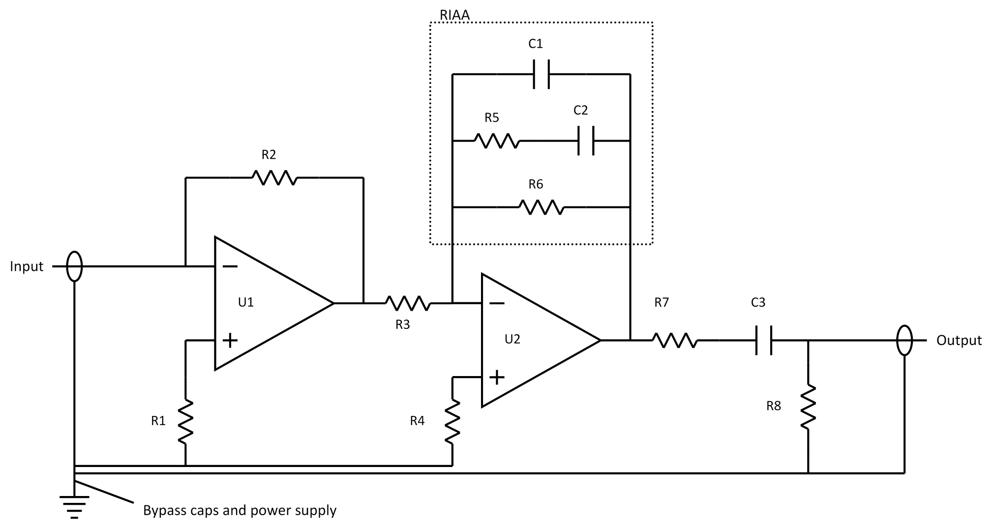
Apart from R8, which must be 47 ohms to satisfy the specified output impedance, the remaining values are based on a few educated estimations and a series of cascading guesses.
| Component | Value | Description |
|---|---|---|
| R1 | 47R | Choose a value to roughly balance the cartridge impedance. |
| R2 | 1k | May be adjusted as needed to set the gain. (see below) |
| R3 | 2k2 | Needs to be low for low noise, but high to avoid loading the output of IC1. |
| R4 | 2k2 | Set to balance R3. |
| R5 | 110k | RIAA |
| R6 | 750k | RIAA |
| R7 | 47R | Defines the output impedance. Isolates the output stage from cable capacitance, improving stability. |
| R8 | 100k | Keeps the output at zero volts DC. Value not critical. |
| C1 | 1.00nF | RIAA |
| C2 | 3.00nF | RIAA |
| C3 | 2.2µF | Output coupling. Must be non-polar. |
| U1 | OP27 | Input stage. |
| U2 | OP27 | Output stage. |
The second stage, with its inverting topology and active equalization is unusual in phono preamps. Buffered as it is here by an op-amp input stage, however, it's ideal. Unlike a non-inverting active stage the gain can fall below unity, allowing the RIAA curve to be traced accurately at high frequencies. With active equalization the signal is attenuated by the variable application of feedback rather than sampling only a portion of the available signal as with a passive stage. The benefit is higher overall gain and lower noise compared to a similar circuit with passive equalization.
The mid-band gain of the second stage is roughly 0.6 R5/R3. As shown it is 33, or 30 dB. The gain of the first stage is R2/Rs, where Rs is the cartridge impedance. When using the OP27, the gain of the first stage should be set to about 30 dB ( R2 = 33 x Rs ) for total gain of 60 dB. Higher gain settings are possible, but not recommended unless you know what you are doing.
Contruction Notes
The phono preamplifier circuit is powered by regulated, low noise, split 12 V supplies. Normally the voltage regulation and filtering is placed on the same board as the phono circuit. The power transformer and rectifier diodes are typically in a separate chassis connected by an umbilical cable. The Construction Guide explains how to put everything together.
Design Manual / Schematic Files
rjm003.geo at yahoo.com